
- #ARDUINO MILLIS INSIDE INTERRUPT HOW TO#
- #ARDUINO MILLIS INSIDE INTERRUPT INSTALL#
- #ARDUINO MILLIS INSIDE INTERRUPT CODE#
If we examine how the Arduino sets up Timer #0, we find it sets a prescale factor of 64 (from the wiring.c file): Before utilizing any timer, several registers must be set. The Atmel ATmega168/328 based Arduino has 3 timers, of which the millis function uses the microcontroller’s Timer #0. Therefore, on the Arduino, each clock cycle is 1/16,000,000 of a second, which is:

A clock cycle is roughly the time it takes for one instruction cycle (there are exceptions). A 16MHz oscillator results in the microcontroller having a clock cycle once every 16-millionth of a second. The typical Arduino has a 16MHz oscillator.
#ARDUINO MILLIS INSIDE INTERRUPT CODE#
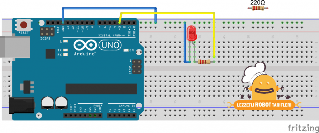
Copy the code given below in that file and save it.First, some background information. Open your Arduino IDE and go to File > New. LOW: This is used to trigger the interrupt when the pin is in a low state.ĬHANGE: This is used to trigger the interrupt when the pin changes its state (HIGH-LOW or LOW-HIGH)Īrduino Sketch: Blinking LED using millis() The following four parameters are used to specify the mode: mode: This denotes the triggering action for the interrupt to occur.Whenever the interrupt will occur this function will be called. It is a special kind of function known as the Interrupt Service Routine which takes in no parameters and also returns nothing. ISR: This is the second argument used to set up an interrupt.You can use any of the ESP32 interrupt pins shown in the diagram above, as a parameter inside this function. For example if setting GPIO2 as an interrupt pin the function will be specified as digitalPinToInterrupt(2). The pin denotes the GPIO associated with the pin which will cause an interrupt to occur. digitalPinToInterrupt(pin): This is a function which takes in the GPIO pin of the ESP board as a parameter inside it.The attachInterrupt() function takes in three arguments: We will use the following function to configure an interrupt in Arduino IDE: attachInterrupt(digitalPinToInterrupt(pin), ISR, mode)

In this tutorial, the interrupt will be triggered when the motion will be detected. For example, there is a Touch Interrupt which happens when touch is detected and a GPIO interrupt when a key is pressed down. But there are few tasks that only execute when a special event occurs such as an external trigger signal to the digital input pin of a microcontroller.Īn external interrupt or a ‘hardware interrupt’ is caused by the external hardware module. For example, we want to perform certain tasks and these tasks execute sequentially in your Arduino program. Interrupts are used to handle events that do not happen during the sequential execution of a program. Installing ESP32 library in Arduino IDE and upload code. If your IDE does not have the plugin installed you can visit the link below:
#ARDUINO MILLIS INSIDE INTERRUPT INSTALL#
Additionally, you also need to install the ESP32 plugin. Thus, you should have the latest version of Arduino IDE. We will use Arduino IDE to program our ESP32 development boards.
#ARDUINO MILLIS INSIDE INTERRUPT HOW TO#


 0 kommentar(er)
